
This chapter provides documentation on the archived traffic detector data as well as the analysis methods used to process and summarize the data. The definition and calculation procedures for the performance measures reported in the Mobility Monitoring Program are also included. The chapter is organized as follows:
- Participating cities and their archived data — presents information on the cities that participated by submitting archived data, including the type of sensor technology used to collect the data, the level of detail of the archived data, and the data elements that were submitted.
- Overview of data processing — provides an overview of the data processing steps used to prepare the data for analysis, including pre-processing, data quality checking, and aggregation to a common data standard, and finally the mobility and reliability analysis.
- Data quality procedures — describes the data quality checks used in preparing the archived data for analysis.
- Congestion and reliability measures — provides definitions and calculation procedures for the performance measures reported in this report.
Participating Cities and Their Archived Data
Public and private agencies from a total of 29 cities participated in the Mobility Monitoring Program by providing archived traffic detector data from 2003 (Table 2). The format and organization of the archived data varies considerably among cities. To provide more consistency and reduce ambiguity, the project team developed some basic guidelines on preferred data formats (Figure 1). These preferred data formats were developed to clarify exactly what data was needed, as well as to “standardize” the archived data (with some minor variation) being submitted to the Program. Some of the preferred data formats and organization arose from how the data were to be processed in the SAS application software. Other details of organization were included because they were already present and consistent in the majority of cities submitting archived data. Note that the preferred data formats reference data elements contained in national ITS standards like the Traffic Management Data Dictionary.7
7 See http://www.ite.org/tmdd/index.asp for more details.
In future years, the project team will encourage use of these preferred data formats to reduce our pre-processing burden and standardize our initial data processing software for all cities. Because participation and data submission is strictly voluntary, however, we are in a position to accept the data format and organization that is most convenient for cities to provide.
| City # | Participating City | Contact Agency/Group | Historical Data Since |
|---|---|---|---|
| 1 | Albany, NY | New York State DOT | 2001 |
| 2 | Atlanta, GA | Georgia DOT | 2000 |
| 3 | Austin, TX | Texas DOT | 2000 |
| 4 | Baltimore, MD | Maryland SHA & Univ. of Maryland | 2003 |
| 5 | Charlotte, NC | North Carolina DOT | 2001 |
| 6 | Cincinnati, OH-KY | ARTIMIS & Kentucky Transportation Cabinet | 2000 |
| 7 | Dallas, TX | Texas DOT & TTI | 2003 |
| 8 | Detroit, MI | Michigan DOT | 2000 |
| 9 | El Paso, TX | Texas DOT | 2003 |
| 10 | Hampton Roads, VA | Virginia DOT & ADMS Virginia | 2000 |
| 11 | Houston, TX | Texas DOT & TTI | 2000 |
| 12 | Los Angeles, CA | Caltrans & PeMS | 2000 |
| 13 | Louisville, KY | Kentucky Transportation Cabinet | 2001 |
| 14 | Milwaukee, WI | Wisconsin DOT | 2001 |
| 15 | Minneapolis-St. Paul, MN | Minnesota DOT & Univ. of Minnesota-Duluth | 2000 |
| 16 | Orange County, CA | Caltrans & PeMS | 2003 |
| 17 | Orlando, FL | Florida DOT | 2001 |
| 18 | Philadelphia, PA | Mobility Technologies | 2001 |
| 19 | Phoenix, AZ | Arizona DOT | 2000 |
| 20 | Pittsburgh, PA | Mobility Technologies | 2001 |
| 21 | Portland, OR | Oregon DOT | 2001 |
| 22 | Riverside-San Bernardino, CA | Caltrans & PeMS | 2003 |
| 23 | Sacramento, CA | Caltrans & PeMS | 2002 |
| 24 | Salt Lake City, UT | Utah DOT | 2002 |
| 25 | San Antonio, TX | Texas DOT | 2000 |
| 26 | San Diego, CA | Caltrans & PeMS | 2001 |
| 27 | San Francisco, CA | Caltrans & PeMS | 2003 |
| 28 | Seattle, WA | Washington State DOT | 2000 |
| 29 | Washington, DC | Maryland SHA & Univ. of Maryland, Virginia DOT & ADMS Virginia | 2002 |
|
PREFERRED DATA FORMATS FOR FHWA’S MOBILITY MONITORING PROGRAM The document summarizes the preferred formats for submitting data to FHWA’s Mobility Monitoring Program. While other formats are acceptable, the following formats are encouraged for unambiguous and efficient data exchange. The required data submissions should include two distinct datasets: 1) actual traffic data records; and 2) traffic sensor location information. Many of the data elements have already been defined by national ITS standards (e.g., Traffic Management Data Dictionary, TMDD) and are indicated as such. File Formats And Organization
Data Elements
Sensor Location Information
Additional Documentation
|
The mobility and reliability measure calculations in the Mobility Monitoring Program are built around estimated travel times for directional freeway routes. However, as Table 3 indicates, nearly all of the participating cities have traffic management centers that collect traffic speeds and volumes at specific points along the freeway route. For 28 of the 29 total cities (all except Houston), the data were collected at point locations using a variety of traffic sensor technologies including single and double inductance loops, microwave radar, passive acoustic, and video image processing. For Houston, link travel times are collected by a toll tag-based system, and these link travel times are supplemented with volume trend data from a limited number of double inductance loops. In many cities, multiple sensor technologies were used to collect the traffic speed and volume data. All of these technologies use a small, fixed zone of detection, and the traffic speed and volume measurements are taken as vehicles pass through this zone. The last section in this chapter describes how these point speeds and volumes are transformed to travel time estimates for directional freeway routes.
Table 3 also indicates the level of detail at which the archived data is submitted to the Mobility Monitoring Program. The time aggregation level varies widely, from 20 seconds in San Antonio to 15 minutes in several areas. In some cases, the data are collected in smaller time intervals (e.g., 20 seconds to 2 minutes) but aggregated to larger time intervals for archiving purposes. Most of the archived data are provided on a per lane basis.
The extent of freeway monitoring coverage is shown in Table 4, which reports the percentage of each city’s freeway system for which archived data are available. The freeway coverage ranges from 6 percent in Dallas to 100+ percent in Milwaukee and Salt Lake City (both cities monitor freeway miles outside of the urban area). The average coverage of freeway centerline miles is 46 percent, whereas the average coverage of freeway lane-miles is slightly higher at 53 percent. Generally speaking, only half of the urban freeway mileage in the 29 participating cities is covered in this report’s analysis. For all 29 cities, there are nearly 3,000 total freeway miles on which real-time traffic data is being collected and archived.
Readers should note that the participating cities were not chosen based on their monitoring coverage, but on their ability to provide archived data. In many cities, this freeway coverage includes the most congested freeways as well as some lightly congested freeway routes. In several cities, the monitoring coverage does not include very congested routes for a variety of reasons (e.g., reconstruction, upcoming deployment, etc.).
| Participating City | Traffic Sensor Technology | Data Level of Detail | |
|---|---|---|---|
| Time | Space | ||
| Albany, NY | loop detectors | 15 minutes | by lane |
| Atlanta, GA | video imaging, microwave radar | 15 minutes | by lane |
| Austin, TX | loop detectors | 1 minute | by lane |
| Baltimore, MD | microwave radar, loop detectors | 5 minutes | by lane |
| Charlotte, NC | microwave radar | 30 seconds | by lane |
| Cincinnati, OH-KY | loop detectors, microwave radar, video imaging | 15 minutes | by direction |
| Dallas, TX | video imaging, loop detectors, microwave radar | 5 minutes | by lane |
| Detroit, MI | loop detectors | 1 minute | by lane |
| El Paso, TX | loop detectors, microwave radar | 1 minute | by direction |
| Hampton Roads, VA | loop detectors, microwave radar | 5 minutes | by direction |
| Houston, TX | probe vehicle (toll tags); also loop detectors, video imaging, and microwave radar | vehicle-based link travel times |
|
| Los Angeles, CA | loop detectors | 5 minutes | by direction |
| Louisville, KY | microwave radar, video imaging | 15 minutes | by direction |
| Milwaukee, WI | loop detectors, microwave radar, video imaging | 5 minutes | by lane |
| Minneapolis-St. Paul, MN | loop detectors | 30 seconds | by lane |
| Orange County, CA | loop detectors | 5 minutes | by direction |
| Orlando, FL | loop detectors | 1 minute | by lane |
| Philadelphia, PA | microwave radar, passive acoustic detectors | 5 minutes | by lane |
| Phoenix, AZ | loop detectors, passive acoustic detectors | 5 minutes | by lane |
| Pittsburgh, PA | microwave radar, passive acoustic sensors | 5 minutes | by lane |
| Portland, OR | loop detectors | 15 minutes | by lane |
| Riverside-San Bernardino, CA | loop detectors, microwave radar | 5 minutes | by direction |
| Sacramento, CA | loop detectors, microwave radar | 5 minutes | by direction |
| Salt Lake City, UT | loop detectors, acoustic detectors, microloops | 15 minutes | by lane |
| San Antonio, TX | loop detectors, acoustic detectors | 20 seconds | by lane |
| San Diego, CA | loop detectors | 5 minutes | by direction |
| San Francisco, CA | loop detectors, microwave radar | 5 minutes | by direction |
| Seattle, WA | loop detectors | 5 minutes | by lane |
| Washington, DC – Maryland – Virginia |
microwave radar, loop detectors (MD) loop detectors (VA) |
5 minutes 1 minute |
by lane by lane |
Source: Conversations with agency representatives and the 2002 ITS Deployment Tracking Survey (http://itsdeployment2.ed.ornl.gov/its2002/default.asp).
| Participating City | Centerline miles | Lane-miles | ||||
|---|---|---|---|---|---|---|
| Instrumented | Total | Coverage (%) | Instrumented | Total | Coverage (%) | |
| Albany, NY | 17 | 104 | 16% | 159 | 550 | 29% |
| Atlanta, GA | 91 | 302 | 30% | 862 | 2,300 | 37% |
| Austin, TX | 23 | 107 | 21% | 146 | 590 | 25% |
| Baltimore, MD | 28 | 290 | 10% | 167 | 1,543 | 11% |
| Charlotte, NC | 15 | 93 | 16% | 89 | 488 | 18% |
| Cincinnati, OH-KY | 54 | 184 | 29% | 367 | 1,035 | 35% |
| Dallas, TX | 19 | 302 | 6% | 151 | 1,904 | 8% |
| Detroit, MI | 110 | 282 | 39% | 751 | 1,810 | 41% |
| El Paso, TX | 31 | 52 | 60% | 193 | 288 | 67% |
| Hampton Roads, VA | 20 | 191 | 10% | 158 | 970 | 16% |
| Houston, TX | 236 | 383 | 62% | 1,764 | 2,548 | 69% |
| Los Angeles, CA | 411 | 463 | 89% | 3,697 | 4,253 | 87% |
| Louisville, KY | 26 | 137 | 19% | 147 | 670 | 22% |
| Milwaukee, WI | 118 | 111 | 106% | 698 | 605 | 115% |
| Minneapolis-St. Paul, MN | 219 | 317 | 69% | 1,194 | 1,595 | 75% |
| Orange County, CA | 178 | 195 | 91% | 1,557 | 1,530 | 102% |
| Orlando, FL | 32 | 166 | 19% | 230 | 775 | 30% |
| Philadelphia, PA | 126 | 352 | 36% | 687 | 2,095 | 33% |
| Phoenix, AZ | 83 | 214 | 39% | 729 | 1,360 | 54% |
| Pittsburgh, PA | 101 | 292 | 35% | 541 | 1,228 | 44% |
| Portland, OR | 54 | 139 | 39% | 245 | 725 | 34% |
| Riverside-San Bernardino, CA | 57 | 143 | 40% | 469 | 918 | 51% |
| Sacramento, CA | 52 | 109 | 48% | 370 | 715 | 52% |
| Salt Lake City, UT | 95 | 84 | 113% | 656 | 545 | 120% |
| San Antonio, TX | 90 | 212 | 42% | 576 | 1,073 | 54% |
| San Diego, CA | 134 | 254 | 53% | 1,065 | 1,848 | 58% |
| San Francisco, CA | 322 | 342 | 94% | 2,349 | 2,455 | 96% |
| Seattle, WA | 120 | 249 | 48% | 889 | 1,763 | 50% |
| Washington, DC | 73 | 309 | 24% | 468 | 1,975 | 24% |
| TOTAL | 2,935 | 6,382 | 46% | 21,374 | 40,149 | 53% |
Source: The estimates for total freeway centerline miles and total freeway lane-miles are from FHWA’s Highway Performance Monitoring System and TTI’s Urban Mobility Study (http://mobility.tamu.edu/ums/).
Real-time traffic data collection and archiving processes have been developed independently in most of the cities and the details of these processes vary among the cities. As a general rule, traffic centers at least have the capability to archive data from their traffic detector systems. In a few cases, this capability is not used because of priorities elsewhere in the traffic center, but it is clear that traffic center software is being constructed with archiving as a function. However, the state of the practice in traffic center archiving is still fairly primitive. The most common practice is to transfer the data to a storage device where they reside in simple text file formats without an active information management system. Quality control is seldom performed at this level and access to the data is provided on a case-by-case basis without the benefit of a query or reporting structure — data are simply provided in whatever file formats are used to store them.
The typical steps from field data collection to data archiving as are follows:
- Traffic data are collected by detectors and accumulated in roadside controllers. These field measurements are typically collected for each individual lane of traffic. At 20-second to 2-minute intervals, the roadside controllers transmit the data to a central location, typically a traffic center.
- Some cities perform quality control on field-collected data, but this checking is simple and based on minimum and maximum range value thresholds.
- Cities that use single inductance loop detectors can measure only volumes and lane occupancies directly. In these cases, speed estimation algorithms are used to compute spot speeds from volumes and lane occupancies. These speed estimation algorithms vary among cities.
- Internal processes at the traffic center aggregate the traffic data to specified time intervals for archival purposes. These time intervals vary from 20 seconds (no aggregation) to 15 minutes. In some cases, the data are also aggregated across all lanes in a given direction at a sensor location.
- The aggregated data are then stored in text files or databases unique to each traffic center. CDs or DVDs are routinely created at the traffic centers to offload some of the storage burden and to satisfy outside requests for the data.
Calibration and maintenance of field equipment and communications are nearly universal problems. The main impediment is lack of resources to devote to these tasks; traffic center budgets are limited and must be used to address a multitude of issues. Calibration—at least to very tight tolerances—is not seen as a priority, given that operators focus on a broad range of operating conditions rather than precise volume and speed measurements. Or in some cases traffic managers may be willing to accept a certain level of data quality to satisfy only their current operations applications. This philosophy may be changing as a result of more stringent data requirements for traveler information purposes (e.g., travel time messages on variable message signs). However, we have found the current data quality requirements used by traffic centers to be quite coarse for supporting their traditional operations activities, such as incident detection and ramp meter control.
Maintenance is a problem (due primarily to funding limitations) even when detectors are known to be producing erroneous or no data. The problem is exacerbated where loop or other pavement-based detectors are used because most agencies are reluctant to shut down traffic on heavily traveled freeways just for detector repair. This is not to say that faulty detectors are never repaired, but maintenance is often postponed to coincide with other roadway activities, which helps spread the cost burden as well.
Field checking of detectors is done periodically but no standardized procedures are used across all cities. If a detector is producing values that are clearly out of range, inspection and maintenance are usually performed. However, calibration to a known standard is rarely, if ever, performed. This means that more subtle errors may go undetected. As most traffic centers typically do not require highly accurate data for most of their operations, this approach is reasonable and practical. Work zones exacerbate these problems and often contractors unknowingly sever communication lines or pave over inductance loops.
Overview of Data Processing
This section presents a brief overview of the data processing steps used to transform the archived data into congestion and reliability statistics. The relatively mundane topic of data processing is included here because of its departure from traditional traffic data monitoring practices. In analyzing the archived traffic data from the 29 participating cities, the project team processed about 6 billion data records, with a total computer processing time best measured in days or weeks.
Figure 2 shows an overview of the data processing steps used to prepare and analyze the archived data. Perhaps the greatest challenge in the data processing was “standardizing” the archived datasets from 29 different cities, or numerous different legacy systems. In many cases, the lack of adequate metadata (i.e., descriptive information about the archived data) complicates the process of properly interpreting and analyzing the archived data. For example, each city’s dataset may use different data error codes to indicate various hardware or software failures. Or similar data error codes could be used by several cities to mean different types of data errors. In other cases, various flaws, nuances, or characteristics in the archived data may be known by the data collector but undocumented, and potentially go undetected by the project team unless careful study was initiated. The experience of the project team indicates that dealing with legacy system data is much more manageable when metadata is used to describe the origin, lineage, characteristics, and subtle nuances of the archived data.
The data processing for the Mobility Monitoring Program is primarily accomplished using SAS software on a Microsoft Windows platform for two reasons: 1) the project team’s previous software programming experience with SAS; and 2) ability and flexibility of SAS to handle a wide range of complex computations on very large datasets. Many other relational database management systems (RDBMS) could also be used to accomplish the same data processing tasks as was performed in SAS.
The data processing flows shown in Figure 2 have been optimized for the use of SAS in generating annual mobility and reliability reports. Some of the data processing steps, however, may be similar for other data archiving and analysis activities. For example, the first step that includes the base code is known as extraction, transformation and loading (ETL) in the data warehouse industry and is a common function for most data warehouse projects. The project team has attempted to standardize the software code as much as possible for ease and automation of data processing. However, the software code is custom-tailored (mostly in the base code) to meet the different formats and organization of submitted archived data.
Figure 2. Overview of Data Processing within Mobility Monitoring Program
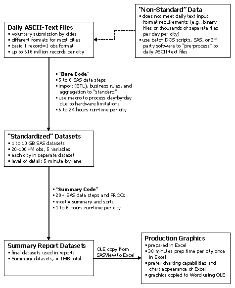
The data processing as shown in Figure 2 would ideally start with daily ASCII-text files that meet the preferred data formats indicated in Figure 1. However, many cities submit data in a form that requires pre-processing (e.g., binary file formats or thousands of separate files per city per day). Pre-processing this non-standard data requires extra steps and time at the beginning to prepare the archived data to be processed using the base code.
Once the submitted archived data meets basic formatting and organization requirements, it is processed using the base code. This software code: 1) imports the data to SAS; 2) performs data quality checking; 3) aggregates detailed data to a common standard (currently 5-minute lane-by-lane); and 4) generates summary statistics on the data quality checking and processing steps. Some of these steps, such as the data quality checks, have been standardized for all cities. Other steps are unique to each city based on the aggregation level and other data characteristics. This step involves the longest amount of processing time, sometimes taking up to 24 hours for the largest cities with the most detailed data (e.g., 20-seconds, lane-by-lane).
The standardized datasets are produced as a result of the base code. The data elements and table structure of these datasets are very similar with a few exceptions (e.g., some cities are 5-minute by-lane, others may be 15-minute by direction). Thus the summary code, which contains the mobility and reliability measure calculations described later in this chapter, has largely been standardized for all cities. The standardized datasets are analogous to the database tables that would be kept on-line in an RDBMS environment.
The summary code performs all mobility and reliability measure calculations, and produces relatively small datasets (less than 1 megabyte total) that are then used to produce the charts and tables shown throughout this report and the city report appendices. Microsoft Excel was selected for the ease of producing report-ready graphics.
In summary, the data processing steps and software code used to analyze the archived data has developed in this way as a result of: 1) previous project team experience; and 2) the specific application of creating annual mobility and reliability reports. Different approaches are very likely given different implementation scenarios and development teams. Several of the data processing steps conducted in the Mobility Monitoring Program may be relevant to other data archiving or data warehouse activities. In particular, the base code contains data quality checking procedures and other steps that are most likely required in other data warehouse efforts. The summary code contains congestion and reliability measure calculations that are described in later in this chapter and may be useful to others developing performance measure programs.
Data Quality Checking
The topic of data quality is included here because of its overall importance in checking and evaluating the validity of archived data. Readers should note that the project team has not been able to systematically assess data accuracy. This means that the traffic speeds and volumes in the archived data could be systematically higher or lower (e.g., ± 10 to 20 percent) than true speeds and still be within the range of possible data values that pass quality control.
Table 5 presents the data quality checks that were used in processing the 2003 archived data. The data quality checks have been developed from these sources:
- Current practices in other traffic centers or data archiving systems;
- Suggested practices recommended in the literature; and
- Practices found to be necessary from project team analysis of the archived data.
These data quality checks can be characterized as basic validity checks and should detect major problems with data errors. More subtle erroneous or suspect data could potentially go undetected with these basic rules. The project team is reviewing the use of more sophisticated data quality checking, and we will continue to balance the sophistication of the data quality checking with the amount of available data processing time. The data quality checks shown in Table 5 may evolve as the project team accumulates more experience with the archived data. More sophisticated quality checks could include tests like these:
- Rapid fluctuations in values across successive time periods;
- Detectors in adjacent lanes at the same location reporting significantly different values or trends;
- Detectors in adjacent upstream or downstream locations reporting significantly different values or trends;
- Detectors from multiple locations reporting the same values (indicative of a system problem);
- Reported values that are significantly different from the location’s history for similar days of the calendar.
The results of these quality control checks are shown in Table 6, which reports the percent of the submitted data that passed the quality control checks. The table presents traffic volume and speed data quality separately, as some of the validity checks could have rejected one of the data values but not the other. Also note that Table 6 only evaluates the validity of the data that was archived and submitted. This table does not reflect data that are missing and were never reported because of various hardware or software failures.
Table 7 summarizes information on data completeness or availability, another dimension of data quality. The data completeness measures the number of available data values to the number of total possible values that one could expect (given the number of sensors and a polling rate). For example, if the data are reported by 5-minute time interval, 288 data values or records per day per detector are to be expected (i.e., 1,440 minutes per day divided by 5-minute periods equals 288 records). Table 7 reports data completeness for the original dataset as submitted by participating cities, as well as the analysis dataset (after quality control and imputation) that is used for mobility and reliability performance measure calculations.
Interested readers should refer to the September 2004 FHWA report on traffic data quality measurement for more details on calculating the validity and completeness measures, as well as several other data quality measures.8
8 Battelle, Cambridge Systematics, and Texas Transportation Institute. Traffic Data Quality Measurement: Final Report. Federal Highway Administration, September 2004.
| Quality Control Test and Description | Sample Code with Threshold Values | Action |
|---|---|---|
Controller error codes
|
If VOLUME={code} or OCC={code} or SPEED={code} where {code} typically equals “-1” or “255” |
|
No vehicles present
|
If SPEED=0 and VOLUME=0 (and OCC=0) |
|
Consistency of elapsed time between records
|
Elapsed time between consecutive records exceeds a predefined limit or is not consistent |
|
Duplicate records
|
Detector and date/time stamp combination are identical. |
|
QC1-QC3: Logical consistency tests
|
If VOLUME > 17 (20 sec.) If VOLUME > 25 (30 sec.) If VOLUME > 250 (5 min.) If VPHPL > 3000 (any time period length) |
|
QC5: Maximum occupancy
|
If OCC > 95% (20 to 30 sec.) If OCC > 80% (1 to 5 min.) |
|
QC6: Minimum speed
|
If SPEED < 5 mph |
|
QC7: Maximum speed
|
If SPEED > 100 mph (20 to 30 sec.) If SPEED > 80 mph (1 to 5 min.) |
|
Maximum reduction in speed
|
If SPEEDn+1 < (0.45 x SPEEDn) |
|
QC8: Multi-variate consistency
|
If SPEED = 0 and VOLUME > 0 (and OCC > 0) |
|
QC9: Multi-variate consistency
|
If VOLUME = 0 and SPEED > 0 |
|
QC10: Multi-variate consistency
|
If SPEED = 0 and VOLUME = 0 and OCC > 0 |
|
QC11: Truncated occupancy values of zero
|
If OCC = 0 and VOLUME > MAXVOL where MAXVOL=(2.932*ELAPTIME*SPEED)/600 |
|
QC12: Maximum estimated density
|
IF ((VOLUME*(3600/NOM_POLL))/SPEED) > 220 where NOM_POLL is the nominal polling cycle length in seconds. |
|
QC13: Consecutive identical volume-occupancy-speed values
|
No more than 8 consecutive identical volume-occupancy-speed values. That is, the volume AND occupancy AND speed values have more than 8 consecutive identical values, respectively. Zero (“0”) values are included in this check. |
|
| Participating City | Validity (%) | |
|---|---|---|
| Volume data | Speed data | |
| Albany, NY | 55% | 54% |
| Atlanta, GA | 94% | 89% |
| Austin, TX | 80% | 56% |
| Baltimore, MD | 99% | 73% |
| Charlotte, NC | 92% | 93% |
| Cincinnati, OH-KY | 76% | 74% |
| Dallas, TX | 100% | 96% |
| Detroit, MI | 100% | 99% |
| El Paso, TX | 55% | 49% |
| Hampton Roads, VA | 75% | 58% |
| Houston, TX | n.a. | 98% |
| Los Angeles, CA | 98% | 99% |
| Louisville, KY | 93% | 93% |
| Milwaukee, WI | 80% | 82% |
| Minneapolis-St. Paul, MN | 83% | 78% |
| Orange County, CA | 98% | 99% |
| Orlando, FL | n.a. | n.a. |
| Philadelphia, PA | 100% | 99% |
| Phoenix, AZ | 72% | 68% |
| Pittsburgh, PA | 100% | 99% |
| Portland, OR | 62% | 85% |
| Riverside-San Bernardino, CA | 96% | 100% |
| Sacramento, CA | 100% | 100% |
| Salt Lake City, UT | 62% | 53% |
| San Antonio, TX | 96% | 84% |
| San Diego, CA | 100% | 99% |
| San Francisco, CA | 100% | 100% |
| Seattle, WA | 85% | 100% |
| Washington, DC | 100% | 98% |
Notes: Validity is reported as the percentage of submitted data values that passed the quality control rules specified in Table 5. See Traffic Data Quality Measurement: Final Report (footnote 8 on page 24) for more details on data quality measure calculation.
| Participating City | Completeness (%) Original Data | Completeness (%) Analysis Data | ||
|---|---|---|---|---|
| Volume data | Speed data | Volume data | Speed data | |
| Albany, NY | 69% | 69% | 38% | 37% |
| Atlanta, GA | 17% | 17% | 57% | 54% |
| Austin, TX | 97% | 97% | 77% | 59% |
| Baltimore, MD | 77% | 77% | 63% | 57% |
| Charlotte, NC | 60% | 61% | 55% | 57% |
| Cincinnati, OH-KY | 47% | 47% | 44% | 41% |
| Dallas, TX | 76% | 76% | 46% | 44% |
| Detroit, MI | 61% | 61% | 61% | 62% |
| El Paso, TX | 98% | 98% | 33% | 33% |
| Hampton Roads, VA | 75% | 75% | 49% | 39% |
| Houston, TX | n.a. | n.a. | n.a. | 56% |
| Los Angeles, CA | 100% | 99% | 98% | 98% |
| Louisville, KY | 82% | 82% | 82% | 76% |
| Milwaukee, WI | 100% | 100% | 80% | 77% |
| Minneapolis-St. Paul, MN | 100% | 100% | 83% | 79% |
| Orange County, CA | 99% | 94% | 97% | 93% |
| Orlando, FL | n.a. | n.a. | n.a. | n.a. |
| Philadelphia, PA | 92% | 92% | 92% | 91% |
| Phoenix, AZ | 89% | 89% | 63% | 60% |
| Pittsburgh, PA | 94% | 94% | 94% | 93% |
| Portland, OR | 98% | 98% | 84% | 83% |
| Riverside-San Bernardino, CA | 71% | 67% | 70% | 67% |
| Sacramento, CA | 88% | 84% | 88% | 83% |
| Salt Lake City, UT | 95% | 95% | 44% | 38% |
| San Antonio, TX | 63% | 63% | 67% | 66% |
| San Diego, CA | 95% | 93% | 95% | 92% |
| San Francisco, CA | 98% | 92% | 97% | 92% |
| Seattle, WA | 79% | 79% | 80% | 81% |
| Washington, DC | 52% | 52% | 33% | 33% |
Note: Completeness is reported as the percentage of data values available for use. It is calculated as the ratio of total available data values to total expected data values. See Traffic Data Quality Measurement: Final Report (footnote 8 on page 24) for more details on data quality measure calculation.
Congestion and Reliability Measure Calculations
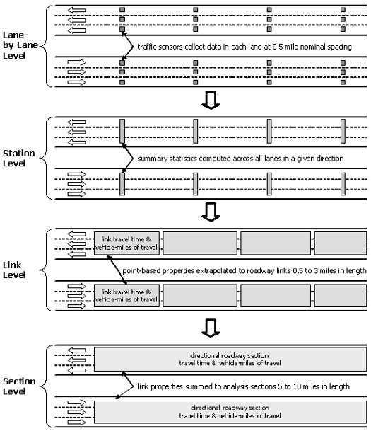
With the exception of Houston, which reported travel times collected with their AVI system, archived data from the participating cities consisted of traffic speeds and volumes collected at various points along the freeway routes. Because the mobility and reliability performance measures are based on travel time, the project team estimated freeway route travel times from the spot speeds. Figure 3 illustrates the process whereby lane-by-lane volumes and speeds are used as the basis for estimating freeway route travel times and vehicle-miles of travel (VMT). The steps are as follows:
- If data are reported by lane, the lane-by-lane data are combined into a “station” (e.g., all lanes in a direction). Traffic volumes are summed across all lanes, and traffic speeds are a weighted average, with weighting based on respective traffic volumes.
- Link properties were estimated from “station” data by assuming that each detector had a zone of influence equal to half the distance to the detectors immediately upstream and downstream from it. The measured speeds were then assumed to be constant within each zone of influence, and travel times were calculated using the equivalent link lengths. VMT were also computed in this way using traffic volume.
- Freeway links were then grouped with other similar adjacent link into analysis sections, which were typically 5 to 10 miles in length. The beginning and end points of analysis sections were typically selected to coincide with major highway interchanges or other locations where traffic conditions were expected to change because of traffic or roadway characteristics.
Travel times for these analysis sections then served as the basis for all subsequent mobility and reliability measure calculations. The specifics of these performance measure calculations are contained later in this section. Readers should note that equations using travel time refer to the analysis section travel times as described above.
Several other aspects and definitions used in preparing the archived data for analysis were:
- Holidays were excluded from the weekday peak period analysis, as holidays were considered to be atypical of normal travel patterns. Holidays are included in several daily total statistics, which also include weekend days. The holidays that are excluded from weekday analyses include:
- New Year’s Day
- Martin Luther King, Jr. Day
- President’s Day/Washington’s Birthday
- Memorial Day
- Independence Day
- Labor Day
- Thanksgiving Day (and the day after)
- Christmas (and day before or after, depending on day of week)
- New Year’s Eve Day
- Fixed and consistent time periods were defined for all cities. These were:
- 12:00 am to 6:00 am – early morning
- 6:00 am to 9:00 am – morning peak
- 9:00 am to 4:00 pm – mid-day
- 4:00 pm to 7:00 pm – afternoon peak
- 7:00 pm to 12:00 am – late evening
- Only mainline freeway detectors were included. Some cities reported ramp data, but these were dropped to maintain consistency across the cities.
Figure 3. Estimating Directional Route Travel Times and VMT From Spot Speeds and Volumes
Congestion Measures
The Mobility Monitoring Program tracks traffic congestion using the three measures below. For most applications, these measures are reported for the peak periods (6 to 9 a.m. and 4 to 7 p.m.):
- Travel time index (measures congestion intensity, also congestion duration when shown by time of day)
- Percent of congested travel (measures congestion extent, also congestion duration when shown by time of day)
- Total delay (measures congestion intensity)
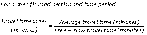
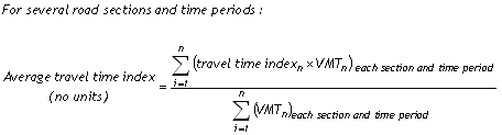
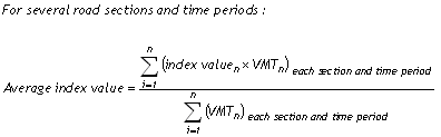
The travel time index is the ratio of average peak travel time to a free-flow travel time (Equation 1). In this report, the free-flow conditions are travel times at a speed of 60 mph. Index values can be related to the general public as an indicator of the length of extra travel time spent during a trip. For example, a value of 1.20 means that average peak travel times are 20 percent longer than free-flow travel times. In this report, the travel time index is calculated for directional freeway sections (as shown in Figure 3), then combined into an areawide average by weighting each freeway section by the respective VMT (Equation 2).
Equation 1
Equation 2
The travel time index can be applied to various transportation system elements with different free-flow speeds, although only freeways were analyzed in the Mobility Monitoring Program. The index can be averaged for streets, freeways, bus and carpool lanes, bus and rail transit, bicycle facilities, and sidewalks. All of these system elements have a free-flow travel time and when crowded, the travel time increases. In a multi-modal context, the VMT in Equation 2 is replaced with person-miles of travel (PMT). An average corridor value can be developed with the number of persons using each facility or mode to calculate the weighted average of the conditions on adjacent streets, freeways, HOV lanes, bus routes and/or rail transit lines. The corridor values can be computed for certain time periods and weighted by the number of travelers to estimate peak-period or daily index values.
The percent of congested travel is calculated as the ratio of congested VMT to total VMT (Equation 3). In this report, a free-flow speed of 60 mph is used as the value below which VMT is considered to be congested.
Equation 3
![]()
Our experience indicates that the use of a 60 mph threshold in the percent congested travel measure may over-represent the magnitude of congestion. In several cities, the spot speeds collected by point-based detectors are less than 60 mph even in light traffic conditions. These point-based detectors are also more likely to record lower speeds than longer distance travel time measurements, due to their common location near entrance ramps and the much greater variation in speed over short sections than long sections. These considerations suggest that a lower speed may be more appropriate for the congestion threshold in this measure when using point-based sensors. Unlike the other congestion measures, congested travel is a binary attribute—travel is either congested or it is not congested, no matter how close the speed is to the congestion threshold. Thus, for a given time period, the VMT is assigned as either congested or not congested, even if the average speeds are just below the congestion threshold. For example, if the nighttime speed limit on an urban freeway system is 55 mph, a significant portion of travel could be categorized as congested without heavy traffic being the cause.
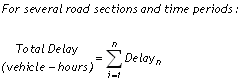
Delay is calculated as the additional travel time that is incurred when actual travel times are greater than free-flow travel times (Equations 4 and 5), expressed in this report as vehicle-hours as well as vehicle-hours per 1,000 VMT. The delay measure can also be expressed in person-hours in a multi-modal context where person travel quantities are known.
Equation 4
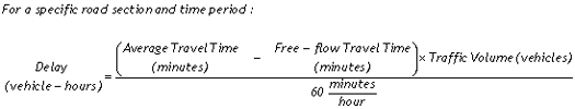
Equation 5
Reliability Measures
The congestion measures in the previous section represent the average and total levels of congestion. In addition to average and total statistics, there is a growing recognition of the need to track variability of congestion and the reliability of travel. The Mobility Monitoring Program tracks these measures for travel reliability:
- Planning time index
- Buffer index
The planning time index is statistically defined as the 95th percentile travel time index (Equation 6) and also represents the extra time most travelers add to a free-flow travel time when planning trips. For example, a planning time index of 1.60 means that travelers should plan for an additional 60 percent travel time above the free-flow travel time to ensure on-time arrival most of the time (95 percent in this report).
Equation 6
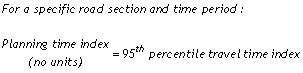
The planning time index is useful because it can be directly compared to the travel time index on similar numeric scales. For example, assume that the peak period travel time index for a particular road section is 1.20, which means that average travel times are 20 percent longer in the peak period than during free-flow conditions. Now assume that the planning time index for that same road and time period is 1.60, which means that 95 percent of all travel times are less than 60 percent longer than during free-flow conditions. In other terms, the planning time index marks the upper limit for the nearly worst (95 percent of the time) travel conditions.
The buffer index represents the extra time (buffer) most travelers add to their average travel time when planning trips (Equation 7). The buffer index is differentiated from the planning time index in these two important ways:
- The buffer index is expressed as a percentage;
- The buffer index represents the extra time between the average travel time and near-worst case travel time (95th percentile), whereas the planning time index represents the extra time between the free-flow travel time and the near-worst case travel time (95th percentile).
Equation 7
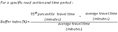
For example, a buffer index of 40 percent means that a traveler should budget an additional 8-minute buffer for a 20-minute average peak travel time to ensure on-time arrival most of the time (95 percent in this report). The 95th percentile travel time was chosen for these reliability measures to represent a near-worst case scenario. For example, the 95th percentile travel time corresponds to a 95 percent on-time arrival rate, which can be simply explained in non-technical terms as “being late for work one day per month.” Other percentiles, such as the 85th or 90th percentile, could be used in this or other applications. Ultimately, the application of the reliability measure will determine the percentile used in its calculation.
Equations 6 and 7 show the reliability measure calculations for a specific road section and time period. For these reliability measures, the road section and time period should be chosen in a way that accurately represents the reliability of interest. For example, an analysis of urban commuting reliability would likely consider freeway sections 5 to 10 miles in length whose endpoints correspond to major freeway or major arterial interchanges. Alternatively, an analysis of intercity travel reliability would consider much longer freeway sections whose endpoints correspond to popular city origins and destinations. The time period(s) should be selected to include conditions of a similar nature and interest to travelers. For example, a buffer index for a typical commuter audience will likely focus on periods throughout the day in which commute travel is made, and should not mix travel times from these different periods. That is, travel times from the evening peak period should not be combined into the same distribution as the morning peak travel times when calculating a 95th percentile.
The average planning time or buffer index values (across several road sections, time periods, etc.) can be calculated by using the VMT as a weighting factor (Equation 8).
Equation 8
The Program also tracks throughput using peak-period and total daily VMT, which is calculated as shown in Figure 3.
Other Considerations for Performance Measure Calculations
The performance measure analysis uses data in a standard format, which currently consists of 5-minute data (all times of the day and days of the year) for 5- to 10-mile freeway sections. This standard format corresponds with the bottom part of the diagram in Figure 3. Combining the estimated travel time values or performance measures from each 5-minute time period is accomplished using VMT as a weighting factor for each time period.
Measures that do not use specific origins and destinations generally provide easier comparisons because these measures are length-neutral and can be applied to a wider variety of situations. If trip-based measures are desired as examples for specific origins and destinations, the performance measures described here can be used with the estimated travel time for a specific trip. This combination of generalized, length-neutral measures as well as specific examples should provide statistics with which most audiences can relate.
There is no single best performance measure and users should resist the urge to select a single measure or index for all situations. Each performance measure reported here addresses different dimensions of traffic congestion or different aspects of reliability. The “dashboard” concept of using a “few good measures” is appropriate, and performance monitoring programs should consider selecting a few (for example, two or three of the five presented here) measures for an executive summary or dashboard report.
This analysis defines fixed-length time periods in which to compute average peak period measures. No single time period will be correct for all analyses, but there are several considerations as follows:
- Peak hour or peak period — Transportation engineers have traditionally used a peak hour to describe congestion, but major urban areas now experience slow speeds for multiple hours in both the morning and the afternoon. In many areas, congestion growth occurs in the hours before or after the traditional peak hour. Use of a single peak hour misses the congestion that occurs during other times, prompting many areas to define a multi-hour peak period.
- Urban area size — Using a 3- to 4-hour peak period for all area sizes may mask congestion for the smaller urban areas. Smaller areas can probably develop useful statistics with only peak hour analyses.
- City-to-city comparison — A consistent peak-period length is necessary for any type of comparison between cities. Comparative studies between urban areas should probably use peak period analyses, rather than only a peak hour.
- Daily or peak comparisons — For national comparisons of reliability trends, a day-to-day comparison is appropriate. For local purposes, where individual trip planning is also an issue, it may be useful to also include travel reliability within an hour or for several segments of a multi-hour peak period.